Enforcing Architecture Rules with Visual Studio
Visual Studio Modeling Projects allow you to quickly generate useful documentation for your design: class diagrams, sequence diagrams, dependency diagrams. All are very nice to look at and useful for getting to know the system. An additional, somewhat hidden feature of Modeling Projects is the ability to enforce architecture rules. In this post I’ll go over the basics of how to enable this and enforce a few simple dependency rules.
My Solution
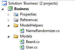
I’ll be enforcing rules on this simple solution:
A User has a Beard. I want ModelHelpers to be a series of static classes used by Models but NOT dependent on the Models namespace. Right now User makes a static call to the NameRandomizer class, sending a string.
Enabling Architecture Rule Validation
Architecture validation occurs on Layer Diagrams in Modeling Projects. Add a Modeling Project to your solution and add a Layer Diagram under that Modeling Project. This will provide you with a blank Layer Diagram.
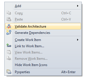
You’re ready to enable validation at this point. This can be done by right-clicking the Layer Diagram surface and selecting the Validate Architecture option or by enabling validation on build. The first option is great for testing your diagram:
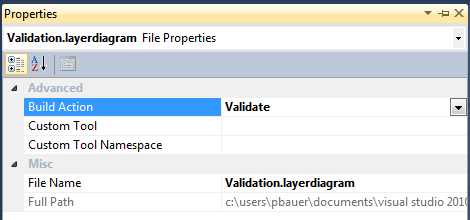
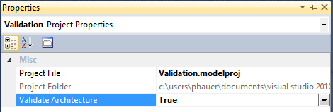
Validating architecture on every build will add a second or two to your build times, but allows you to better enforce architecture errors. The solution will not build if the Layer Diagram rules are broken. To enable validation on build, set the relevant Layer Diagram property Build Action to “Validate” AND set the Validate Architecture Property on the containing Modeling Project to “True”.
Populating the Layer Diagram
The Layer Diagram is meant to be a UML model of your system. It will be blank on create, but you have the ability to drag and name entities from the Toolbox or the Architecture Explorer (no naming required). Dragging items from the Architecture Explorer is easier and quicker. (Aside: Reviewing the Architecture Explorer regularly is a good way to manage your design as the solution grows. It’s also helpful for spotting Namespace errors or irregularities.)
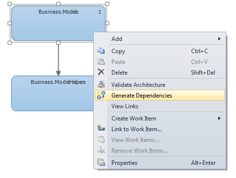
Items can be linked together to show dependencies. Again, you can do this manually or automatically by right-clicking an item and selecting the Generate Dependencies option. This will create UML (an arrow pointing from parent to child, or a bi-directional arrow) denoting a dependency. Note that this option will generate dependencies for the selected item; it will not generate dependencies for items that have the selected item as a child.
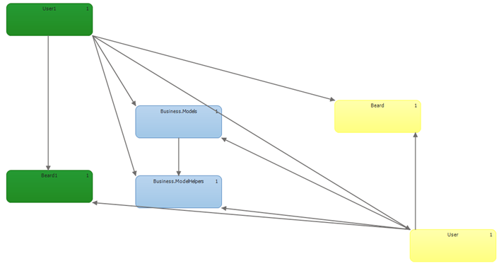
You can specify dependencies for Assemblies, Namespaces, Classes, and members and calls within classes. I’d recommend multiple Layer Diagram files, one for each level or, if its complex, possibly each dependency. The diagrams quickly become spaghetti as ALL dependencies will be enforced (if a member depends on another member, it will depend on that member’s Class and Namespace). Below is a diagram with multiple layers enforced.
Architecture Errors
Suppose we validate the below diagram by making Business.ModelHelpers dependent on Business.Models. When we attempt to build we’ll see multiple errors, one for each rule we’ve violated (where each arrow is a rule).
Alone, these errors are not too descriptive. Double-clicking an error will take you to the specific line of code in violation, which works well.
Resources
How to Validate .NET Code Against Layer Diagrams (MSDN) – from this page: Validation options are NOT available in VS Pro and Express.
